
Language
8S 30000mAh UAV Battery
The 8S 30000mAh UAV battery combines 840Wh of nominal energy with a 28V nominal supply. Its reference body is 215 × 94 × 77mm at 2,752g. For an eight-series aircraft, the selection questions are whether the 60A continuous-current design target covers the mission and whether every device on the bus accepts the 34V charging cut-off voltage.
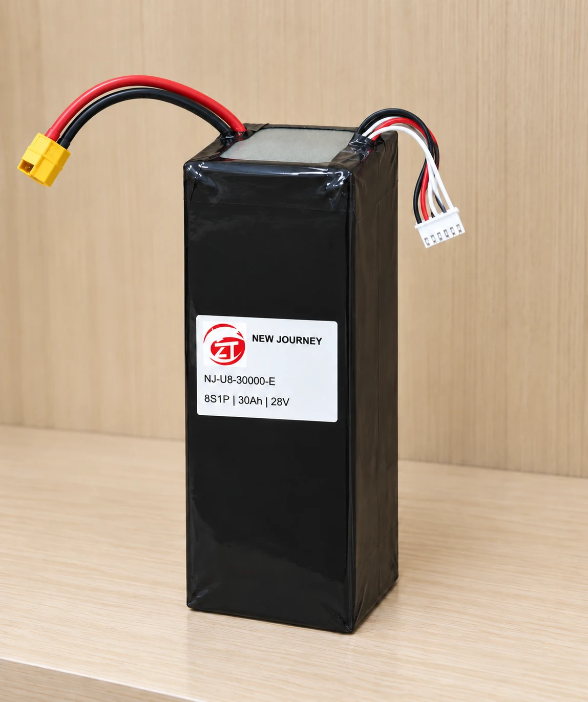
- 28VNominal voltage
- 840WhNominal energy
- 34VCharging cut-off
- 60AContinuous design target
Technical specifications
| Configuration | 8S1P · 30Ah (30000mAh) |
|---|---|
| Nominal voltage | 28V |
| Nominal energy | 840Wh · calculated from nominal voltage × rated capacity |
| Charging cut-off voltage | 34V · 4.25V per cell |
| Standard charge current (design) | 15A · 0.5C |
| Continuous discharge design target | 60A · 2C |
| Burst discharge design target | 90A · 3C for 10 seconds |
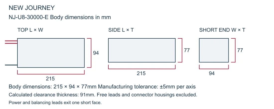
| Body dimensions L × W × T (design) | 215 × 94 × 77mm · ±5mm per axis; free leads and housings excluded |
| Calculated finished-pack weight | 2,752g · production tolerance ±10g from the approved nominal configuration |
| Calculated pack specific energy | 305.2Wh/kg · nominal energy ÷ calculated complete-pack mass |
| Calculated clearance thickness | 91mm · cell growth allowance, separate from initial body tolerance |
| Lead arrangement | About 150mm to connector entry; power and sensing at opposite sides of the same short face |
| Balancing interface | Nine contacts · B0 to B8 |
| Cell model | EDP8887188-30Ah |
| Main connector | Select the complete mating pair, lead specification and polarity for the aircraft |
Compare the energy gain with the weight your aircraft can carry
For an aircraft already designed for 8S, this 30Ah version adds 210Wh over the 6S 30Ah option for 658g more calculated pack weight. It carries 840Wh while retaining the same 60A continuous-current design target. Use route energy and loaded climb demand to judge the trade-off. The additional series cells do not make it a direct replacement in a six-series aircraft.
Charging voltage and charger matching
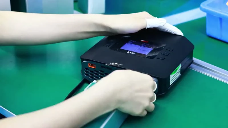
A fleet charging station needs to match the 34V charging cut-off and 15A standard-charge design setting. Check the actual programme rather than selecting one solely because it says 8S; a 33.6V endpoint is different. The charger, nine-node balancing adapter and main charge connection should be specified together, especially if existing equipment must be retained.
Continuous and burst discharge current
More series cells add voltage and energy, not a higher current rating. The targets remain 60A continuous discharge current and a 90A burst for 10 seconds. If an 8S aircraft draws more than the smaller platform during loaded climb, the unchanged current limit matters. Send a time-based current trace to match the battery, main lead and connector to the complete mission.
Pack weight and aircraft mass budget
Protect the payload requirement by comparing installed mass, not Ah alone. Calculated pack weight is 2,752g, including 2,600g of cells and 152g of assembly allowance. Calculated pack specific energy is 305.2Wh/kg. The tray, restraints and aircraft-side wiring add further mass. Cable length or connector changes need to be included before the nominal pack weight is agreed.
Battery dimensions and installation clearance
Check cover closure and battery removal before reusing a mount. The body is 215 × 94 × 77mm; both power and sensing leads leave one short end, from opposite sides. Leave access to grip the plugs without pulling their wires. A separate 91mm calculated clearance thickness accounts for cell growth and should be considered alongside the initial body dimensions.
Series and parallel configuration
An incorrect balancing adapter can prevent an otherwise suitable battery from working with the charging station. The 8S1P arrangement uses eight 30Ah pouch cells and nine nodes, B0 to B8. Match the node order, connector polarity and main charging circuit. Specify any BMS or aircraft communication requirements separately from the balance harness.

Frequently asked questions
Does 30Ah mean the 6S and 8S versions store the same energy?
No. The nominal energy is 630Wh at 21V for 6S and 840Wh at 28V for 8S. Capacity stays the same while series voltage changes.
Can an ordinary 33.6V 8S charge profile be used?
It has a different endpoint from this configuration's 34V limit. Confirm the specified cell profile, charger settings and balancing connection rather than treating the two voltages as interchangeable.
Which value should be used for the flight controller's low-voltage action?
Set it from the aircraft's loaded behaviour, cell balance and required reserve. The sum of cell cutoff values is an electrical boundary, not a ready-made landing threshold.
Battery pack assembly
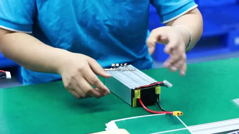
Fleet replacements need repeatable mounting and connector positions. The cell arrangement, end insulation and lead exits can be specified around the aircraft tray, with the balancing harness kept accessible for charging. Include the cover and strap positions when requesting a sample layout.

Discuss your aircraft configuration
Share your 8S power-bus specification, loaded mission current, tray drawing and charging-station models with New Journey. We can help align the battery layout, main connector and balancing harness.